3 steps to configure Modbus
26.03.2021
Step 1: Create a new IO driver
First things first, open your Integraxor project and navigate to the Tag → IO Driver tab (inside of the Integraxor Project Editor). Create a new driver by entering its name and selecting the corresponding Modbus Address. You can enter any name you want.
In case you have a device with Modbus RTU communication, type the name of the corresponding PC COM port (where you have connected your Modbus RTU device) into the “Address” column.
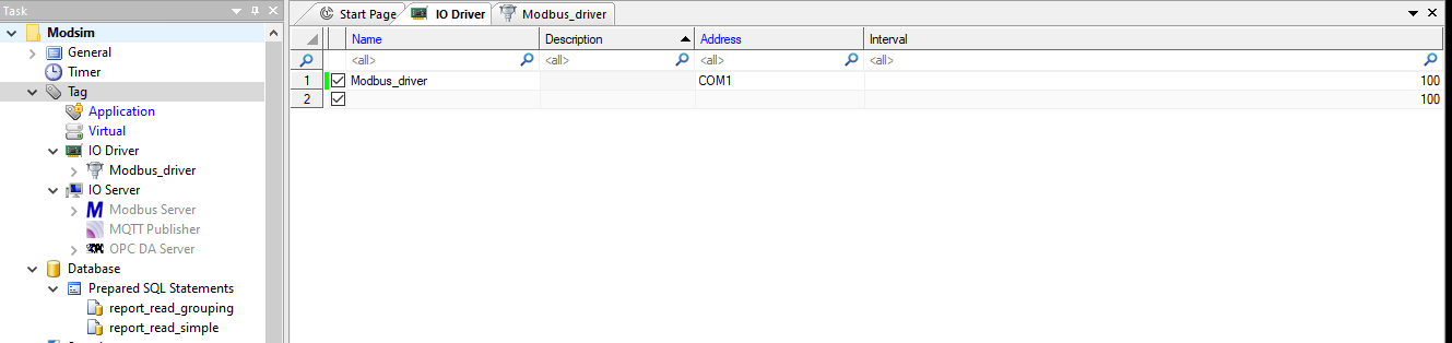 In our example we have a device connected to the COM1 port, so we type “COM4” into the “Address” column.
In case you have a device with Modbus TCP communication, type the Modbus Slave IP address and port into the “Address” column. Address and port number are separated with a colon.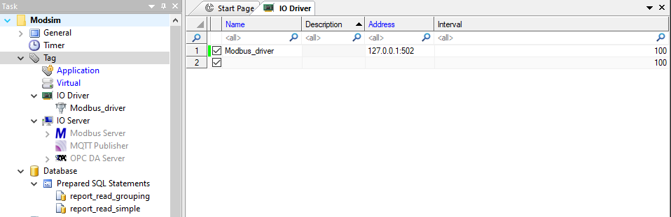
In our example we use the local connection with a Modbus simulator (address 127.0.0.1 and port number 502). In your case you will have an actual address instead of 127.0.0.1.
Step 2: Create a device
Navigate to the Tag → IO Driver → “Your driver name”.
Enter any device name you want inside the “Name” column. Choose the driver polling rate (how frequently you want to read Modbus data) by selecting an option inside the “Timer” column. Inside of the “Driver” column choose “Modbus” option. In the “Address” column enter the Modbus slave address of your device. If communication with your device requires additional settings, you can enter them on the right side of this page. If you use a device with Modbus TCP/IP communication, on the right side you will see corresponding Ethernet settings.
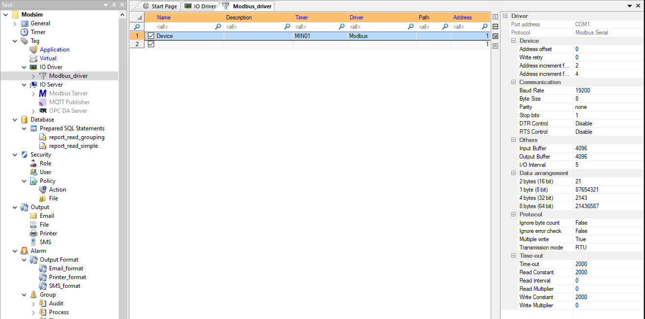 In our example we have configured a Modbus device connection with 1 minute period (“Timer” column value is set to MIN1) with the device at the 1 address.
Step 3:
Navigate to the Tag → IO Driver → “Your driver name” → “Your device name”. Here you can create variables you will need to read or write to the Modbus device.
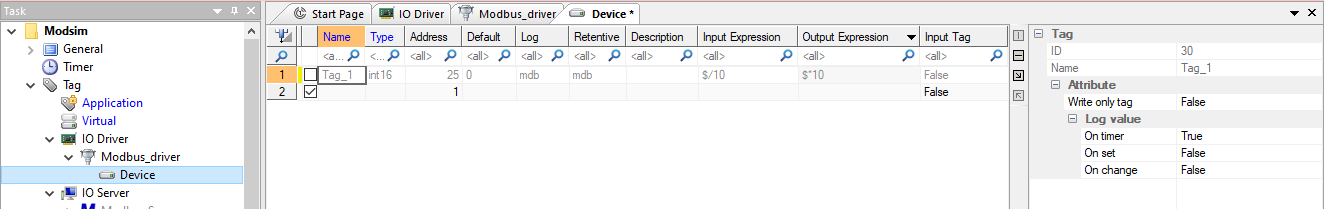
To create a variable:
- enter its name in the “Name” column;
- its type in the “Type” column;
- its Modbus register address in the “Address” column;
- its default value in the “Default” column;
- whether you want to periodically log the value of this variable inside the database (requires additional database configuration and enables the ability to show variable values in a chart) by choosing the name of the database in “Log” column;
- whether you want to save the last variable value which will be restored after the restart of the system (requires additional database configuration) by choosing the name of the database in “Retentive” column;
- if you want you can add your own description of the variable (which will not be seen anywhere outside of the editor and the runtime), you can do it by writing inside of the “Description” column;
- if your variable needs to be converted before being used in the project (for example, you need to divide or multiply the value before using it) or being written into the device, you can enter the corresponding expression inside the “Input expression”/”Output expression” columns. For example, your device stores 10.1 as 101. So you receive the value 101 through Modbus, but need to use the value 10.1. In this case just write $/10 inside the “Input expression” column. If you want to write it back to the device, write $*10 inside the “Output expression” column;
- if your variable is a Modbus slave input register, choose the “true” value inside the “Input Tag” column.
To test whether the communication has been successfully configured, launch the project by clicking on the “Run Project button” and navigate to the “Watch” tab of the IntegraXor SCADA Server (runtime) and type the name of the variable inside the search box. If everything is OK, you should be able to see the value of this variable.
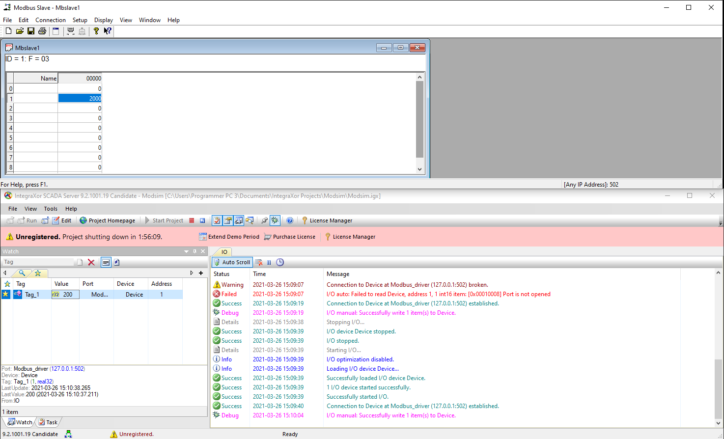 The value of the variable being read is 200 (“Watch” tab is in the bottom left side of the screenshot).